Chapter one ..Chapter two ..Chapter three .Chapter four.Chapter five ..Chapter six
Have questions????--Inquiry Form
Introduction

Electronic Power Angling Devices for a Venetian Blind
I will present two
types of mini-blind angling devices for retrofit
purposes. One is structurally more complicated to
construct because of the miniature size requirements, the other
is structurally simple, essentially in the form of a
plastic box. Both use essentially the same electronic
components, with the only difference between the two being in the
motor control circuitry. Since a larger gear motor with a
greater current draw is used in the box shaped electronic power
angler, it therefore requires transistors that can handle the
higher current load of the gear motor, or a couple
relays in place of the low current rated transistors used in the
“Electronic Power Angling Rod” motor direction control
circuitry. The larger gear motor is most often cheaper and most
important, it is available from various sources, where as the
miniature dc gear head motors are usually very expensive,
excepting surplus which are available only intermittently
in the surplus market place, and are quickly sold out.(More
about miniature gear motors in chapter five containing
the components parts list, component parts descriptions
& specifications, and component prices.)
I will present the structurally simple angler device second. If you are not good at working on model type projects, then the box shaped electronic power angler should be the easiest to construct. The “Electronic Power Angling Rod” is allot like building a model airplane or ship, except the more complicated task of manufacturing your own parts from scratch, such as long hollow aquarium Lee’s plastic tubes, Sharpie pens, Bic pens, cup hooks, paper fasteners, and the like modified as various parts. The only parts that are premanufactured are the electronic components, which you have to wire together on a perforated board one half inch in diameter by up to seventeen inches long. Although it looks simple in structure, it is not super simple to build. You must have patience when building the “electronic power angling rod”. It took many trial prototypes and much hands-on experimentation to accomplish the construction of the present “electronic power angling rod” which I invented and applied for a patent on June 5, 1995 and it was granted on February 18, 1997.
I
II
Each prototype was an experimental discovery in progress. The first prototype I constructed was not immune to lightning flashes at night and lightning caused the mini blind to open in the middle of the night. This was cured with one simple capacitor which slowed down the light detector response to the lightning flash. Another problem consisted of the mini blind angling open and closing several times at the approach of night and day light. The problem, I discovered only existed on the west side or east side of the house, where the sun descends in the west and ascends in the east. As the sun descends or ascends at the horizon, its rays pass through terrestrial objects such as mountains,. hills, trees, buildings, and the like, creating a varying light output that goes from bright light to low light. I solved the problem by incorporating a timer delay circuit, which disallows all light detection signals after the very first signal it receives. The timer circuit allows time, to pass that ambiguous period at dusk and / or dawn.
III
Another problem came up when I
manually closed the blind during the afternoon to block the suns
rays from entering the room. I didn’t reangle
the blind slats to the open horizontal position, before
night fall. That night, the blind slats angled to the
opened horizontal position. I only incorporated a
circuit that detected light and conversely its opposite, darkness.
The circuit blindly sent a signal to the motor control
circuitry, which promptly did the opposite of what was desired,
it angled open. The angling device was now responding backwards,
angling the slats closed during the day and opened at night.
I therefore incorporated a kind of memory and gate
arrangement to tell it not to respond to the light detection
circuitry when the angled position of the slats was already
in the desired position for day or night. This
did not interfere with the manual operation of the device.
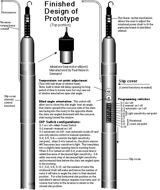
The situation of closing the blinds when the sun shined directly on the window prompted me to incorporate a circuit which could detect temperature variations, and respond by temporarily closing the slat angle until temperature reduced to an adjustable preset point as the suns rays moved out of the window area.
As with all the
rest of the circuitry I constructed for the “electronic
power angling rod”, I had to design from scratch a circuit
that would use less than (10) ten micro amperes of power in
standby. I desperately wanted the “electronic power
angling rod” to run on batteries for a long time
before replacement was needed. There wasn’t much
out there when I first started experimenting in the hobbyist
world for ultra micro powered circuits. I then
discovered that many CMOS ICs could be powered on less
than (5) micro amperes, such as the 4013 dual D flip-flop
used as the memory / gate. I also discovered that the 2N6028
Programmable Unijunction Transistor (P.U.T.), had a leakage
current rate of 1.5 micro amperes, and that its gate could be
controlled with the leakage current supplied across a reverse
biased signal diode such as the 1N4148. This allowed me to build
a simple circuit consisting of a phototransistor circuit coupled
across the anode and gate of the P.U.T., keeping the gate more
positive when enough light shined on the phototransistor. When
light receded, the gate would become negative as leakage current
flowed from the reversed biased diode, with its anode connected
to ground, subsequently charging a 0.1 uF. capacitor connected
between the anode and the gate of the P.U.T. When the gate
reached its trigger voltage, because the P.U.T.’s anode is
more positive than the gate, it causes the P.U.T. to
conduct briefly with a surge of current through the cathode of
the P.U.T. by discharging another 0.1 uF. capacitor connected
between the anode and ground (negative), with the anode
connected to a high value resistor, in the 5 million ohm
range, electrically connected to the positive side of the battery. The
negative resistance inherent in the design of the P.U.T.
contributes to the falling off characteristic of the current
detected at the cathode.
IV
And finally, not satisfied with
what I designed so far, I decided the angling device needed an
infrared light (IR), controlled remote control receiver. I
tried making the Sharp IR receiver modules you can buy at Radio
Shack run on less current, but was unsuccessful in reducing their
power requirements below (1) one miliampere, that’s (1000)
one thousand micro amperes. So I designed from
scratch an IR receiver which detects the frequency of the pulsed
IR signal and triggers its control output at the detection of
the frequency and amplitude of the modulation of the
transmitters signal. Its some what crude, but works quite well
for what its used for, the “electronic power angling rod”,
and there’s nothing digital about it, its completely analog.
Its fairly immune to high brightness light sources and also to
flouresent lights as long as the lights aren’t right next to
the IR sensor.
The construction of the
“electronic power angling rod” requires the use of
a Dremel tool, although it is possible to do without it, the
tool does make construction a little easier. You will
definitely need an Xacto knife or some other cutting device that
can be used to cut thin walled plastic tubing. The tubing used as
the containment housing for the “electronic power angling
rod” comes from aquarium / pet retail outlets. It is
sold under the name of Lee’s Tubes, and is used for the pump
filter systems in fish tanks. (More on the plastic tubes in
chapter five containing the components parts list, component
parts descriptions & specifications, and component prices.) You
will also need some super glue.
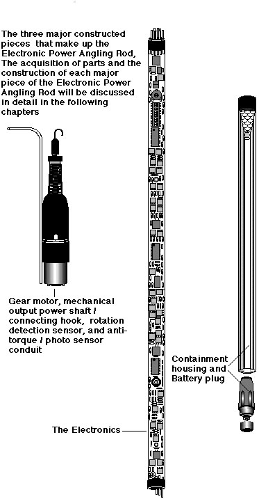
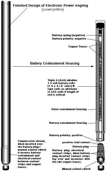
The first chapter will cover the electronics with schematic break down of each circuit. The second chapter will cover the component layout (you can lay the components out on the perforated board any way you wish), and tips for construction. The third chapter will cover the construction of the gear motor / sensors housing (upper portion). This is the most complicated structural part of the “electronic power angling rod” to build, requiring some patience. The fourth chapter will cover construction of the main housing and construction of the battery containment housing and battery / manual control plug and how all the components just mentioned are integrally pieced together into the “electronic power angling rod”. In addition the fourth chapter will tell you how to paint your finished “electronic power angling rod”. And finally the fourth chapter will show you how to install your finished product. The fifth chapter will cover the parts list, component parts description & specifications. Finally, the sixth chapter will cover the box shaped angling apparatus and its construction.
V
VI
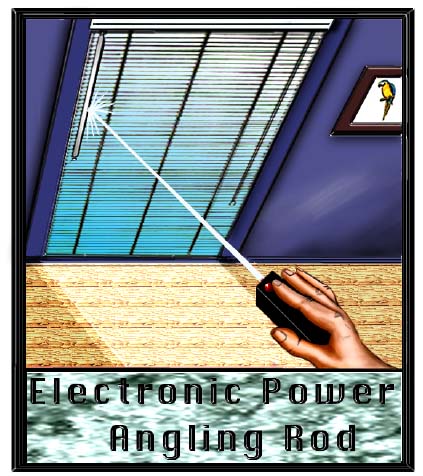
The Electronic Power Angling Rod Listed in the following are the major features of the micro-powered Electronic Power Angling Rod
Features
1. The Electronic Power Angling Rod will automatically angle open and close a horizontal mini blind, in a cyclic manner , dictated by the setting and rising of the sun.
2. The Electronic Power Angling Rod can be manually controlled at any time by the push of a button switch, or galvanic touch switch located at the bottom of the rod / wand or can be remotely controlled at a distance by an infrared light signal.
3. The Electronic Power Angling Rod remembers where it should be angled in respect to light conditions, and responds accordingly to keep the automatic function in accord with those conditions, no matter what angle, open or closed, the blind is set to manually.
4. The Electronic Power Angling Rod can be programmed to respond to bright hot sunlight. The already angled open blind (daylight position), will temporarily angle to the closed position when a preset temperature level is reached, and then open again as the heat level drops back down below the temperature setting. The temperature trigger point to which the device responds is adjustable.
5. The Electronic Power Angling Rod can be programmed to work only in the manual mode (automatic function is set to off position).
6. The Electronic Power Angling Rod can be programmed to reorient the blind angle starting and stopping positions. For example, the user has the choice of opening and closing the blind angle from top closed, to horizontal open or bottom closed to horizontal open.
7. The Electronic Power Angling Rod can be programmed to respond to different ambient light levels. This prevents the device from responding to artificial light sources such as porch lights, city street lights, and the like. The hysteresis, inherent in the electronics, and with an added delay timer circuit included, which temporarily disables the light level detectors, until fluctuating light levels pass, prevents any oscillation effects. If not for these features, the mini blind could repeatedly cycle open and close several times at the approach of dawn or dusk, especially as the rays pass through obstructions, ie. trees, bushes, buildings, houses, mountains, hills, etc. .
8. The Electronic
Power Angling Rod can be programmed to angle open at five
predetermined positions. They are approximately a 20 degree angle,
30 degree angle, 45 degree angle, a fully open horizontal angle
and back to a 45 degree angle, but with the blind angle
oriented in the opposite direction. Angles are of course
dependent upon the initial angle, which should be horizontal.
VII
The Electronic Power Angling Rod
Listed in the following are the major advantages of the micro-powered Electronic Power Angling Rod
Advantages
1. The Electronic Power Angling Rod functions in an autonomous manner, with every component tied together in one self contained housing, batteries included.
2. The Electronic Power Angling Rod is micro-powered by a set of AAA alkaline batteries for up to three years before replacement is needed. The Electronic Power Angling Rod draws a minuscule 4 to 9 micro-amperes, except the two seconds or less, the motor is on, from two to four times a day.
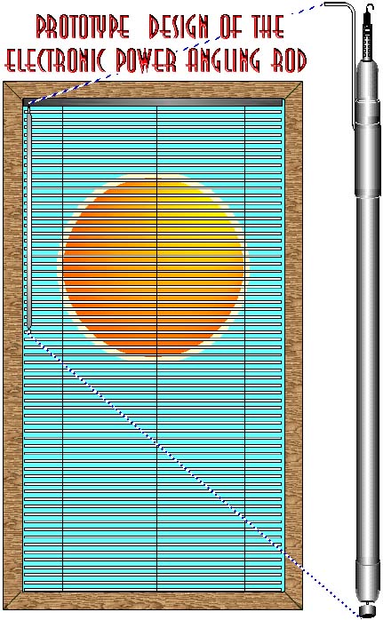
3. The Electronic Power Angling Rod can retrofit to most any brand of mini blind manufactured today. The rotating output shaft connected to the gearhead, can be raised or lowered by means of a telescopic linear rachet device built into the rotating output shaft. This allows the Electronic Power Angling Rod to be adapted to the many varying lengths of input shafts protruding from the head rail on the multitude of existing and new mini blinds that have and are being manufactured today.
4. The Electronic Power Angling Rod melds into the total horizontal blind design, just as the manually adjustable rod / wand it replaced.
5. The Electronic Power Angling Rod is completely solid state. There are no relays, external or internal mechanical position switches, only one moving part, the motor gear head combination which is connected to a short hollow shaft containing a small magnet. The magnet triggers an adjacent Hall effect sensor for counting the number of rotations needed to position the angle of the mini blind.
6. All the electronic components are off-the-shelf, inexpensive, and available in through-hole or surface mount.
7. Because the Electronic Power Angling Rod is self contained with no unsightly box shaped housings, dangling wires, external position switches, it therefore requires no labor intensive installation. There are manufacturers that make and install at great cost, $200.00 to $800.00 per window, similar devices. Their electric anglers are boxy shaped or if hidden, must be installed by experts which install gear head motors in the mini blind housing and then install wiring in the wall to a control box and plug-in wall adaptor. These customized mini blind angling devices are obviously not affordable by everyone.
8. The Electronic Power Angling Rod can be installed by the user, and attached to the mini-blind in just minutes.
9. The Electronic Power Angling Rod can help save energy. In winter, by insuring passive solar heating through windows during daylight hours and closing at night to help insulate from heat loss. In summer, by closing during direct sunlight exposure, to help lower air conditioning costs.
10. The Electronic Power Angling Rod can be a psychological deterrent to opportunistic burglars, by allowing them to think a dwelling or business is occupied, when in reality is not. 11. And finally, the Electronic Power Angling Rod can be remotely controlled at a distance, by infrared light signal. This is highly advantageous if the window is located in a high place. No need for very long angling rods / wands that extend down to where they can be reached .
VIII

VIV
Have questions????--Inquiry Form